


Why Is Capital Equipment Maintenance Important?
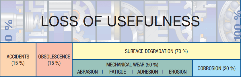
Capital equipment is typically one of the most expensive assets for any business and as such, regular maintenance will extend the life of capital equipment, reduce capex, and mitigate the risk of unplanned downtime. In our article, why is filtration important, we discussed how 70% of component replacements or 'loss of usefulness' is due to surface degradation. In hydraulic and lubricating systems, 20% of these replacements result from corrosion with 50% resulting from mechanical wear. This underscores the vital importance of filtration and industrial lubrication.
Assets have value – if they are maintained well the value of capital equipment will not depreciate as quickly
Defer replacement costs – well maintained capital equipment will last longer, so you will not need to replace them as often
Minimize breakdowns – equipment that breaks can completely disrupt productivity and cost the business a lot of money. Maintaining the equipment will reduce the likelihood of any breakdowns
Sources of Contamination
Built in contaminants from components:
- Assembly of system
- Cylinders, fluids, hydraulic motors, hoses and pipes, pumps, reservoirs, valves, etc
Generated contaminants:
- Assembly of system
- Operation of system
- Break-in of system
- Fluid breakdown
External ingression:
- Reservoir breathing
- Cylinder rod seals
- Bearing seals
- Component seals
Contaminants introduced during maintenance:
- Disassembly/assembly
- Make-up oil
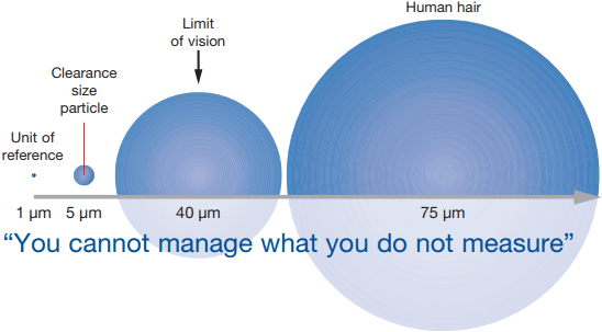
The Micrometre “µm”
‘Micron’ = micrometre = µm
The micrometre is the standard for measuring particulate contaminants in lubricating and fluid power systems.
1 micron = 0.001 mm (0.000039 inch)
10 micron = 0.01 mm (0.0004 inch)
Smallest dot you can see with the naked eye = 40 µm
Thickness of a human hair = 75 µm
Types of Contamination
Silica
Hard, translucent particles often associated with atmospheric
and environmental contamination, e.g., sand, dust.
Bright Metal
Shiny metallic particles, usually silver or gold in colour,
generated within the system. Generated contaminants are
products of wear and often cause additional component wear
and accelerated fluid breakdown.
Black Metal
Oxidized ferrous metal inherent in most hydraulic and
lubricating systems; built-in contaminant and genereated
within the system by wear.
Rust
Dull orange/brown particles often seen in oil from systems
where water may be present, e.g., oil storage tanks.
Fibers
Contaminants most commonly generated from paper and
fabrics, e.g., shop rags.
Cake of Fines
Very large concentrations of ‘silt’-size particles coat the analysis
membrane and build-up into a cake. The cake obscures the
larger particles on the membrane making contamination
evaluation impossible.
Water Contamination in Oil
Water contamination in oil systems causes:
- Oil breakdown, such as additive precipitation and oil oxidation
- Reduced lubricating film thickness
- Accelerated metal surface fatigue
- Corrosion
Sources of water contamination:
- Heat exchanger leaks
- Seal leaks
- Condensation of humid air
- Inadequate reservoir covers
- Temperature reduction causes dissolved water to turn into free water
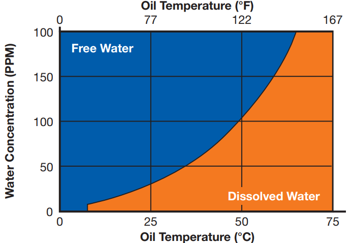
To minimize the harmful effects of free water, water concentration in oil should be kept as far below the oil saturation point as possible.
10,000 PPM - 1%
1,000 PPM - 0.1%
100 PPM - 0.01%
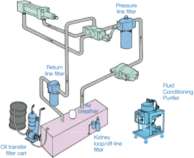
Filter Types and Locations
Pressure Line
- To stop pump wear debris from travelling through the system
- To catch debris from a catastrophic pump failure and prevent secondary system damage
- To act as a Last Chance Filter (LCF) and protect components directly downstream of it
Return Line
- To capture debris from component wear or ingression travelling to the reservoir
- To promote general system cleanliness
Kidney loop/off-line
- To control system cleanliness when pressure line flow diminishes (i.e. compensating pumps)
- For systems where pressure or return filtration is impractical
- As a supplement to in-line filters to provide improved cleanliness control and filter service life in high dirt ingression systems
Reservoir Air Breather
- To prevent ingression of airborne particulate contamination
- To extend system filter element service life
- To maintain system cleanliness
Additional filters should be placed ahead of critical or sensitive components
- To protect against catastrophic machine failure (often non-bypass filters are used)
- To reduce wear
- To stabilize valve operation (prevents stiction)
Flushing Filter
- To remove particles that have been built-in to the system during assembly or maintenance before start-up
- To remove large particles that will cause catastrophic failures
- To extend ‘in-service’ filter element life
Flushing Recommendations
The aim of flushing is to remove contamination from the inside of pipes and components that are introduced during system assembly or maintenance. This is accomplished by passing clean fluid through the system, usually at a velocity higher than that during normal operation to pick up the particles from the surface and transport them to the flushing filter. Omission or curtailment of flushing will inevitably lead to rapid wear of components, malfunction and breakdown.
Reynolds Number (Re): A non-dimensional number that provides a qualification of the degree of turbulence within a pipe or hose.
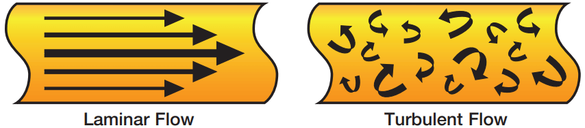
Laminar Flow - Re < 2,000
Transitional Flow - Re 2,000 - 4,000
Turbulent Flow - Re > 4,000
For effective flushing procedures the Reynolds Number (Re) should be in excess of 4000. The flow condition in a pipe or hose can be assessed using Reynolds Number (Re) as follows:
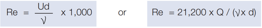
Re = Reynolds Number
U = Mean flow velocity (m/s)
d = Pipe internal diameter (mm)
V = Kinematic viscosity of fluid in cSt (mm2 /s)
Q = Flow rate (L/min)
Cyclic Stabilization Test for Measuring Filter Performance
Concept:
As opposed to ISO 16889 that only tests filters under steady state conditions, the Cyclic Stabilization test is used to evaluate hydraulic filter performance under typical stressful operating cyclic conditions such as:
- Flow surges
- Pressure peaks
- Cold starts
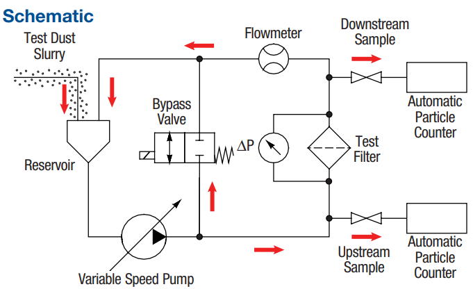
Cyclic Stabilization Test (CST) measures a filter’s ability to clean up a contaminated system under cyclic flow (25 to 100% of rated flow) and contaminant loading conditions.
CST ISO 4406 Cleanliness Code ratings are based on the stabilized cleanliness achieved at 80% of the net terminal pressure drop, considered the worst operating condition.
Because of technological developments related to the products, systems, and/or services described herein, the data and procedures are subject to change without notice. Please consult your Pall representative to verify that this information remains valid.