


Keep up to date with the latest filtration solutions for industrial manufacturing markets
5000

Filtration and Separation Solutions for Industrial Manufacturing
Industrial manufacturing processes can be extremely sensitive to the presence of contaminants. Having effective and reliable monitoring, separation, and filtration at various points in industrial manufacturing is essential to improving end-product quality, extending equipment life, and reducing costly downtime. We provide premium industrial filter solutions and separation systems specifically designed to streamline process efficiency and improve business performance throughout the production process.
Explore Our Industrial Filtration Solutions
Filter Rental Services
A locally available fleet of mobile equipment for short and long-term rental to protect critical process assets, safeguard output and improve product quality.
Featured products for various filtration applications
-
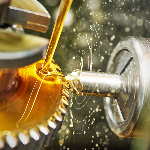
Hydraulic & Lubrication Filtration
-
Oil Purifiers
-
Varnish Removal in Oil Systems
-
Fluid Condition Monitoring
Supralon Replacement Filter Elements
The direct replacement for existing Pall Coralon and Ultipor III filter elements and some alternative makes of filter housing

2X better particle removal efficiency compared to ßx(c)≥1000 rated filters

10X better efficiency than common ßx(c)≥200 rated filters

Significantly fewer passes required to reach target cleanliness level

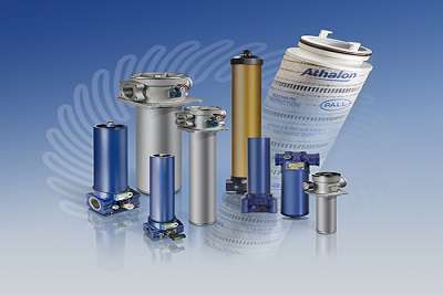
Athalon™ Filters
The Ultimate in Hydraulic & Lube Oil Filter Performance
Our easy to install Athalon™ pressure and return line housings contain filter elements made from inert, inorganic fibers in a coreless, Laid-Over Pleat (LOP) design configuration that maximizes the available filter capacity to extend filter service life. The filter element is resistant to high cyclic flow stress and dirt loading, has a Betax(c) ≥ 2000 efficiency rated (the highest rating in the industry today), and has anti-static properties to prevent the detrimental effects of electrostatic discharge. Athalon filter housings are also quick, safe, and easy to maintain by unscrewing the filter cap rather than removing the complete filter bowl.
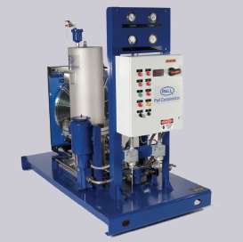
Water contamination promotes corrosion and fluid system component wear, resulting in reduced component life and increased maintenance costs. It also degrades fluid properties, leading to reduced lubricity and load carrying ability, oil oxidation and the resultant formation of acids, and additive precipitation. The consequences are reduced fluid service life and increased fluid procurement and disposal costs
Pall’s oil purification solutions remove 100% of free water 80% of dissolved water, they also remove 100% of free and entrained gases and up to 80% of dissolved gases.
Select the Pall oil purifier for:
- High performance water, gas and particulate removal
- Extension of fluid service life
- Minimized corrosion within systems
- Reduced fluid disposal
- Reduced operating costs
- Increased equipment reliability
- Simple automated operation
- Remote monitoring option
Watch the demonstration of dehydration technology associated with the HNP
Varnish is the thin, insoluble film deposit that forms on oil-wetted surfaces inside a turbine lube system, including bearings and servo valves. It’s formation is often attributed to higher operating temperatures, smaller fluid reservoirs, high cyclic service, and fluid base stocks that have lower solvency for varnish precursors.
You can’t see it, but you know it’s there taking your hydraulics system down one component at a time.
When varnish forms in turbine oils, the effects can be devastating to the operation and availability of the equipment, and may include:
- Sluggish controls and servo valves stiction, which can lead to expensive repairs or replacement
- Costly downtime from unscheduled outages
- Start-up delays from unresponsive control systems
The demand for reliability, availability, and seamless operation of today’s power turbines requires an efficient, easy and reliable method for removing varnish not only from the oil, but also from the wetted metal surfaces inside the machine
“You can’t manage what you can’t measure”
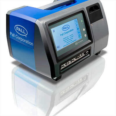
Pall monitoring solutions include fluid cleanliness monitors and filter condition indicators. Additionally, Pall in-line water sensors provide real-time measurement of dissolved water content in oils, warning of the potential formation of damaging free water in the gearbox and lube oil system. Pall can also apply years of accumulated knowledge to help translate raw data into meaningful information.
Literature Library
Document Type
Search
Results
Document
Document Type
Language
Resources
Why is Filtration Important?
According to a study by Dr. E. Rabinowicz of M.I.T., 70% of component replacements or "loss of usefulness" is due to surface degradation. 20% of these replacements are due to corrosion, and 50% are due to mechanical wear.
Particles generated as a result of abrasive wear are work hardened; thus they become harder than the parent surface. If these particles are not removed by proper filtration, they will recirculate and cause additional wear. This "chain reaction of wear" will continue and result in premature system component failure unless high-performance filtration is applied to break the chain.