


Explore Microelectronics Products and Solutions
Our products support to make existing processes easier, faster and better with innovative technologies.
Your Partner for Microelectronics Filtration and Purification
Microelectronics filtration solutions reduce operating and maintenance costs, drastically improve equipment OEE and availability, extend chemical life, reduce defects, and maximize product quality and yields.
Pall Filtration Systems have successfully integrated their proven systems in microelectronics to reduce the cost, increase the reliability and maximize the efficiency of electronic manufacturing processes. As operations have increased in such a degree, particulate, impurity, and contamination control has become extremely critical in order for efficient production processes. Solving these challenges directly impacts operation uptime, maintenance frequency, product quality, life of capital equipment and overall business performance.
Semiconductor device yields have long been impacted by impurities in fluid and gas streams. As process nodes continue to shrink and features sizes and geometries become more complex, sensitivity to contamination during manufacturing process has increased significantly. Impurities such as metal, particulates and hydrocarbons directly impact each step of the process thereby resulting in higher process rinse up volumes, more chemical usage, costly downtime and significant reduction in line yield
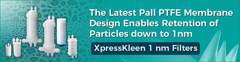
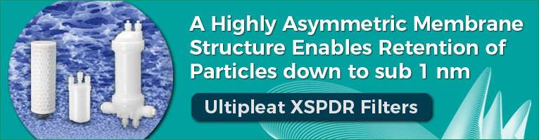
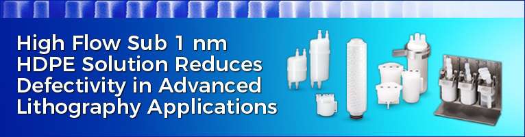
Advanced Node semiconductor manufacturing require extremely clean fluid streams thereby driving need for high-end filtration and purification solutions. Tighter contamination control can significantly improve yield, a marginal improvement in yield means millions of $’s of net profit for the fab.
-
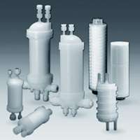
Compact Cartridge Filters & Housings
Download: -
UltiKleen Series
Download: